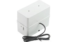
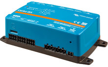
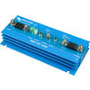
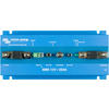
Victron BMS 12/200 Battery Management System
Availability:
Sold out
Our service

Order hotline
+49 (0)9181 / 330 100Mon. - Sat.: 8:00 - 20:00 hrs
Specialist advice
ARRANGE CALLBACKMon. - Fri.: 9:00 - 16:00 o'clock
Secure payment with SSL encryption
Free return
Up to 5% bonus with the Berger advantage card
Product details
| for 12.8 Volt lithium iron phosphate batteries | Especially designed for vehicles and boats |
Product description
BMS 12/200 for 12.8 Volt lithium iron phosphate batteries Specially designed for vehicles and boats
Why lithium iron phosphate?
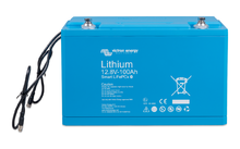
The lithium iron phosphate (LiFePO4 or LFP) battery is the safest of the regular lithium iron battery types. The rated voltage of an LFP cell is 3.2 V (lead acid: 2 V/cell). A 12.8 V LFP battery therefore consists of 4 cells connected in series and a 25.6 V battery consists of 8 cells connected in series
Reasons for the need for a battery management system (BMS):
1. An LFP battery will be damaged if the voltage applied to the cell falls below 2.5V
2. An LFP battery is damaged when the voltage applied to the cell rises above 4.2V. Lead-acid batteries may also be damaged if they are over-discharged or overcharged, but this usually does not happen immediately. A lead-acid battery will recover from a deep discharge, even if it has been left in a discharged state for several days or even weeks (depending on battery type and brand)
3. The cells of an LFP battery do not automatically equalize at the end of the charge cycle. The cells in a battery are never 100% equal. For this reason some cells are fully charged or discharged earlier than others during the cycle. These differences become more pronounced if the cells are not equalised from time to time. In a lead-acid battery, a small current continues to flow even when one or more cells are fully charged (the main effect of this current is to split water into water and oxygen). With the help of this current, the other cells whose state of charge is lagging behind are also charged and thus the state of charge of all cells is balanced. The current that flows through an LFP cell when it is fully charged is almost zero. Less charged cells are not fully charged for this reason. The difference between the individual cells can become so extreme over time that, although the total voltage of the battery is within the limits, some cells are destroyed due to overvoltage or undervoltage
An LFP battery must therefore be protected by a BMS that actively balances the individual cells and thus prevents undervoltage or overvoltage
Robust
A lead-acid battery will fail prematurely due to sulphation in the following cases
- If it is left in an insufficiently charged state for a long time (the battery is rarely or never fully charged).
- When left in a partially charged or, worse, fully discharged condition (yacht or motorhome during winter)
An LFP battery does not need to be fully charged. In fact, operating life is slightly increased if the battery is only partially charged instead of fully charged. This is a significant advantage of LFP batteries compared to lead-acid batteries. Other advantages include a wide operating temperature range, excellent cycling, low internal resistance and high efficiency (see below)
The LFP battery is therefore the best choice for demanding use
Efficient
For many applications (especially off-grid solar and/or wind power plants), the energy efficiency can be of crucial importance. The energy efficiency of a charge cycle (discharge from 100% to 0% and recharge to 100%) of an average lead-acid battery is about 80%. In contrast, the energy efficiency of a charge cycle of an LFP battery is 92%. The charging process of a lead-acid battery becomes particularly inefficient when the 80% state of charge mark is reached. This leads to energy efficiency levels of only 50%. This value is even lower in solar systems, where energy reserves are required for several days (the battery is in operation at a state of charge between 70% and 100%). An LFP battery, on the other hand, still achieves an energy efficiency of 90%, even when in a shallow state of discharge
Size and weight Space
savings of up to 70 % Weight savings of up to 70
Infinitely flexible
LFP batteries are easier to recharge than lead-acid batteries. The charging voltage can vary between 14 V and 16 V (as long as no cell exceeds 4.2 V). In addition, these batteries do not need to be fully charged. For this reason, several batteries can be connected in parallel and no damage will occur if some batteries are less charged than others. Our 12 V BMS supports up to 10 batteries in parallel (BTVs are single chained)
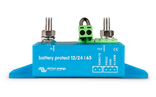
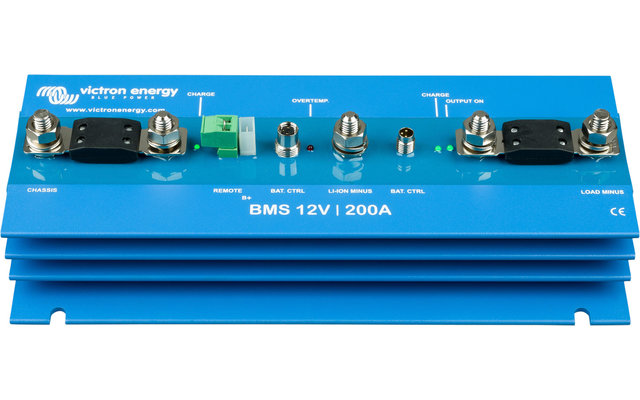
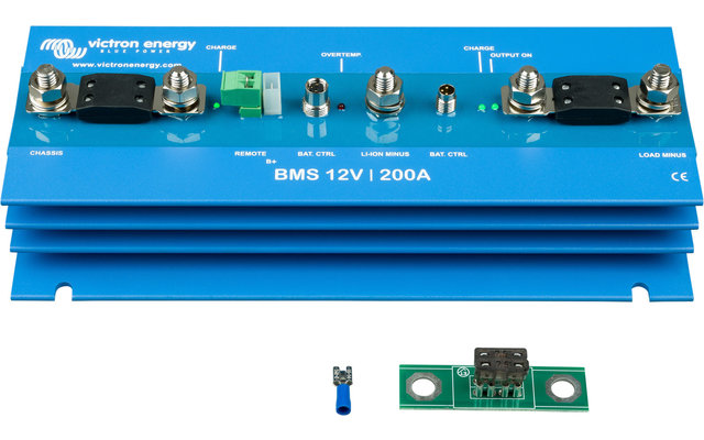
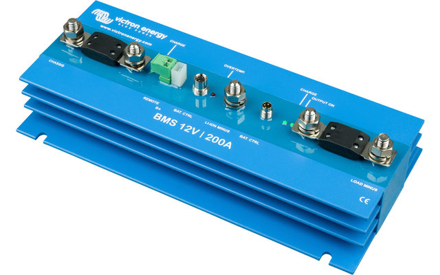
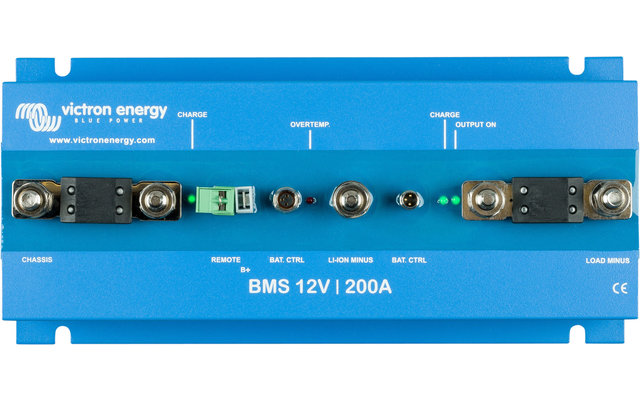
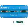
A 12 V BMS that protects the alternator (and wiring) and delivers up to 200 A for any DC load (including inverters and inverters/chargers)
Alternator/battery charger input (Power Port AB)
1. The first task of Power Port AB is to prevent the load connected to the LFP battery from discharging the starter battery. This function is similar to that of a Cyrix battery coupler or Argo FET battery isolator. Current can only flow to the LFP battery if the input voltage (= voltage at the starter battery) exceeds 13 V.
2. No current can flow from the LFP battery back to the starter battery. This prevents possible damage to the LFP due to excessive discharge
3. Excessive input voltages and transients are reduced to a safe level
4. The charge current is reduced to a safe level in case of cell imbalance or overheating
5. The input current is electronically limited to approximately 80% of the nominal value of the AB fuse. A 50 A fuse therefore limits the input current to 40 A. Choosing the right fuse therefore entails the following:
a. The LFP battery is protected from excessive charging current (important in case of a low capacity LFP battery)
b. The alternator is protected against overload in the case of a high capacity LFP battery bank (most 12V alternators overheat and fail if operated for more than 15 minutes at maximum output power)
c. The charging current is limited so that the current carrying capacity of the cabling is not exceeded. The maximum rated value of the fuse is 100 A (which limits the charging current to about 80 A)
Output/input load/battery charger (Power Port LB)
1. maximum current in both directions: 200 A uninterruptible
2. Peak discharge current electronically limited to 400 A
3. Disable battery discharge whenever the weakest cell drops below 3V
4. The charge current is reduced to a safe level in case of cell imbalance or overheating.
Why lithium iron phosphate?
The lithium iron phosphate (LiFePO4 or LFP) battery is the safest of the regular lithium iron battery types. The rated voltage of an LFP cell is 3.2 V (lead acid: 2 V/cell). A 12.8 V LFP battery therefore consists of 4 cells connected in series and a 25.6 V battery consists of 8 cells connected in series
Reasons for the need for a battery management system (BMS):
1. An LFP battery will be damaged if the voltage applied to the cell falls below 2.5V
2. An LFP battery is damaged when the voltage applied to the cell rises above 4.2V. Lead-acid batteries may also be damaged if they are over-discharged or overcharged, but this usually does not happen immediately. A lead-acid battery will recover from a deep discharge, even if it has been left in a discharged state for several days or even weeks (depending on battery type and brand)
3. The cells of an LFP battery do not automatically equalize at the end of the charge cycle. The cells in a battery are never 100% equal. For this reason some cells are fully charged or discharged earlier than others during the cycle. These differences become more pronounced if the cells are not equalised from time to time. In a lead-acid battery, a small current continues to flow even when one or more cells are fully charged (the main effect of this current is to split water into water and oxygen). With the help of this current, the other cells whose state of charge is lagging behind are also charged and thus the state of charge of all cells is balanced. The current that flows through an LFP cell when it is fully charged is almost zero. Less charged cells are not fully charged for this reason. The difference between the individual cells can become so extreme over time that, although the total voltage of the battery is within the limits, some cells are destroyed due to overvoltage or undervoltage
An LFP battery must therefore be protected by a BMS that actively balances the individual cells and thus prevents undervoltage or overvoltage
Robust
A lead-acid battery will fail prematurely due to sulphation in the following cases
- If it is left in an insufficiently charged state for a long time (the battery is rarely or never fully charged).
- When left in a partially charged or, worse, fully discharged condition (yacht or motorhome during winter)
An LFP battery does not need to be fully charged. In fact, operating life is slightly increased if the battery is only partially charged instead of fully charged. This is a significant advantage of LFP batteries compared to lead-acid batteries. Other advantages include a wide operating temperature range, excellent cycling, low internal resistance and high efficiency (see below)
The LFP battery is therefore the best choice for demanding use
Efficient
For many applications (especially off-grid solar and/or wind power plants), the energy efficiency can be of crucial importance. The energy efficiency of a charge cycle (discharge from 100% to 0% and recharge to 100%) of an average lead-acid battery is about 80%. In contrast, the energy efficiency of a charge cycle of an LFP battery is 92%. The charging process of a lead-acid battery becomes particularly inefficient when the 80% state of charge mark is reached. This leads to energy efficiency levels of only 50%. This value is even lower in solar systems, where energy reserves are required for several days (the battery is in operation at a state of charge between 70% and 100%). An LFP battery, on the other hand, still achieves an energy efficiency of 90%, even when in a shallow state of discharge
Size and weight Space
savings of up to 70 % Weight savings of up to 70
Infinitely flexible
LFP batteries are easier to recharge than lead-acid batteries. The charging voltage can vary between 14 V and 16 V (as long as no cell exceeds 4.2 V). In addition, these batteries do not need to be fully charged. For this reason, several batteries can be connected in parallel and no damage will occur if some batteries are less charged than others. Our 12 V BMS supports up to 10 batteries in parallel (BTVs are single chained)
A 12 V BMS that protects the alternator (and wiring) and delivers up to 200 A for any DC load (including inverters and inverters/chargers)
Alternator/battery charger input (Power Port AB)
1. The first task of Power Port AB is to prevent the load connected to the LFP battery from discharging the starter battery. This function is similar to that of a Cyrix battery coupler or Argo FET battery isolator. Current can only flow to the LFP battery if the input voltage (= voltage at the starter battery) exceeds 13 V.
2. No current can flow from the LFP battery back to the starter battery. This prevents possible damage to the LFP due to excessive discharge
3. Excessive input voltages and transients are reduced to a safe level
4. The charge current is reduced to a safe level in case of cell imbalance or overheating
5. The input current is electronically limited to approximately 80% of the nominal value of the AB fuse. A 50 A fuse therefore limits the input current to 40 A. Choosing the right fuse therefore entails the following:
a. The LFP battery is protected from excessive charging current (important in case of a low capacity LFP battery)
b. The alternator is protected against overload in the case of a high capacity LFP battery bank (most 12V alternators overheat and fail if operated for more than 15 minutes at maximum output power)
c. The charging current is limited so that the current carrying capacity of the cabling is not exceeded. The maximum rated value of the fuse is 100 A (which limits the charging current to about 80 A)
Output/input load/battery charger (Power Port LB)
1. maximum current in both directions: 200 A uninterruptible
2. Peak discharge current electronically limited to 400 A
3. Disable battery discharge whenever the weakest cell drops below 3V
4. The charge current is reduced to a safe level in case of cell imbalance or overheating.
| Technical data | |
| Maximum number of 12.8 V batteries | 10 |
| Maximum charge current, Power Port AB | 80 A at 40°C |
| Maximum charging current, Power Port LB | 200A at 40°C |
| Maximum uninterrupted discharge current, LB | 200A at 40°C |
| Peak discharge current, LB (short circuit proof) | 400 A |
| Approximate reverse voltage | 11 V |
| General information | |
| No load current during operation | 10 mA |
| Power consumption, when switched off | 5 mA |
| Power consumption after blocking battery discharge due to low cell voltage | 3 mA |
| Operating temperature range | -40 to +60°C |
| Humidity, maximum | 100% |
| Humidity; average | 95% |
| Protection, electronics | IP65 |
| DC connection AB, LB and battery minus | M8 |
| DC connection Battery-Plus | Flat tab 6,3 mm |
| LEDs | |
| Battery is charged via Power Port AB | green |
| Battery is charged via Power Port LB | green |
| Power Port LB active | green |
| Overheating | red |
| Housing | |
| Weight | 1.8 kg |
| Dimension (HxWxD) | 65x120x260 mm |
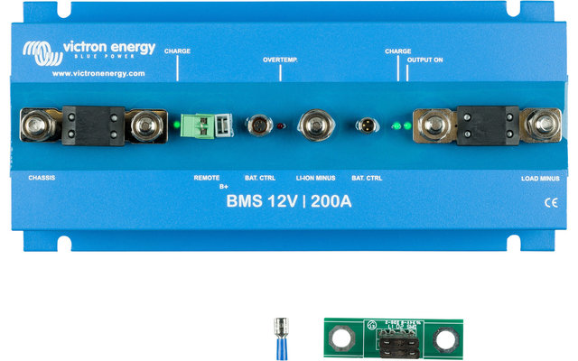
Features
| Type battery | Accessories |
Our service
Order hotline
+49 (0)9181 / 330 100Mon. - Sat.: 8:00 - 20:00 hrs
Specialist advice
ARRANGE CALLBACKMon. - Fri.: 9:00 - 16:00 o'clock
Secure payment with SSL encryption
Free return
Up to 5% bonus with the Berger advantage card