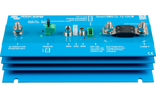
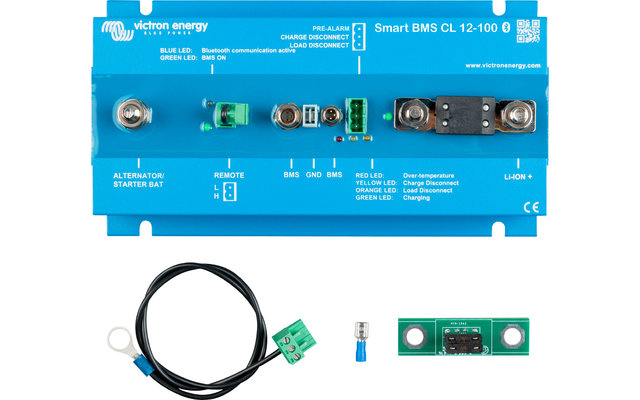
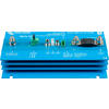
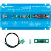
Victron Smart BMS CL Battery Management System 12V 100A
Our service

Order hotline
+49 (0)9181 / 330 100Mon. - Sat.: 8:00 - 20:00 hrs
Specialist advice
ARRANGE CALLBACKMon. - Fri.: 9:00 - 16:00 o'clock
Secure payment with SSL encryption
Free return
Up to 5% bonus with the Berger advantage card
Product details
| mi Li-Ion battery protection | Protects the alternator from overload |
Product description
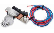
Battery Management System
The BMS is connected to 12.8 V Victron LiFePO4 (LFP) batteries. Up to 5 batteries can be connected in parallel. Can be used as an on/off switch for the system
Alternator and battery protection
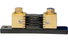
The input current is electronically limited to approximately 90% of the fuse rating. A 100 A fuse, for example, will therefore limit the input current to approximately 90 A. Choosing the correct fuse will: a. Protect the LFP battery from excessive charging current (important for a low capacity LFP battery). b. Protect the alternator from overloading in the case of a high capacity LFP battery bank (most 12V alternators will overheat and fail if run at maximum output for more than 5 minutes)
Starter battery protection
This function is similar to that of a Cyrix battery combiner or Argo FET battery isolator. Current can only flow to the LFP battery when the input voltage (= voltage at the starter battery) exceeds 13V. And no current can flow back from the LFP battery to the starter battery, preventing possible damage to the LFP battery due to excessive discharge
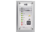
Li-Ion Battery Protection
Excessive input voltages and transients are regulated down to a safe level. The Smart BMS CL stops charging in the event of cell overvoltage or overtemperature. It has three outputs, similar to the
miniBMS
Load disconnect output
The load disconnect output is normally high and becomes free floating when the cell is live (standard 2.8 V/cell, adjustable at the battery between 2.6 V and 2.8 V per cell). Maximum current: 10 mA. The load output can be used to control the remote on/off input of a battery protector, inverter, DC/DC converter, or other loads
Pre-alarm output
The pre-alarm output can be used as a warning when the battery voltage is low, and it will trigger just before the load disconnect output is disabled due to cell undervoltage. The pre-alarm output can be used to drive a relay, LED or buzzer. It can be configured as a continuous or intermittent signal. The pre-alarm output is normally free floating and will go high if the cell is threatened with undervoltage (standard 3.1 V/cell, adjustable at the battery between 2.85 V and 3.15 V per cell). Maximum current: 1 A (not short circuit proof) Minimum delay between pre-alarm and load disconnect is 30 seconds
Charge disconnect output
The output of the charger is normally high and will free float in case of imminent overvoltage or overtemperature of the cell. Maximum current: 10 mA. The Charger output is not suitable for driving an inductive load such as a relay coil. The "Charger" output can be used to control the following devices: The remote on/off switching of a charger, a Cyrix Li charger relay, a Cyrix Li-ct battery combiner. (Note: in some cases an interface cable is required, please refer to the manual)
Remote on/off input
The remote on/off input controls the charging process via the alternator. When switched off, charging via the alternator is disabled, while the BMS functionality remains active, so that all loads and chargers can continue to operate regardless of the state of the remote input. When the "System On/Off switch" is activated via VictronConnect, the BMS functionality is also deactivated. It consists of two terminals: Remote L and Remote H. A remote on/off switch or a relay contact can be connected between H and L. Alternatively, terminal H can be connected to battery. Alternatively, terminal H can be connected to battery positive or terminal L to battery negative
Explosion protection
No relays, but MOSFET switches, and therefore no sparks
Technical data
The BMS is connected to 12.8 V Victron LiFePO4 (LFP) batteries. Up to 5 batteries can be connected in parallel. Can be used as an on/off switch for the system
Alternator and battery protection
The input current is electronically limited to approximately 90% of the fuse rating. A 100 A fuse, for example, will therefore limit the input current to approximately 90 A. Choosing the correct fuse will: a. Protect the LFP battery from excessive charging current (important for a low capacity LFP battery). b. Protect the alternator from overloading in the case of a high capacity LFP battery bank (most 12V alternators will overheat and fail if run at maximum output for more than 5 minutes)
Starter battery protection
This function is similar to that of a Cyrix battery combiner or Argo FET battery isolator. Current can only flow to the LFP battery when the input voltage (= voltage at the starter battery) exceeds 13V. And no current can flow back from the LFP battery to the starter battery, preventing possible damage to the LFP battery due to excessive discharge
Li-Ion Battery Protection
Excessive input voltages and transients are regulated down to a safe level. The Smart BMS CL stops charging in the event of cell overvoltage or overtemperature. It has three outputs, similar to the
miniBMS
Load disconnect output
The load disconnect output is normally high and becomes free floating when the cell is live (standard 2.8 V/cell, adjustable at the battery between 2.6 V and 2.8 V per cell). Maximum current: 10 mA. The load output can be used to control the remote on/off input of a battery protector, inverter, DC/DC converter, or other loads
Pre-alarm output
The pre-alarm output can be used as a warning when the battery voltage is low, and it will trigger just before the load disconnect output is disabled due to cell undervoltage. The pre-alarm output can be used to drive a relay, LED or buzzer. It can be configured as a continuous or intermittent signal. The pre-alarm output is normally free floating and will go high if the cell is threatened with undervoltage (standard 3.1 V/cell, adjustable at the battery between 2.85 V and 3.15 V per cell). Maximum current: 1 A (not short circuit proof) Minimum delay between pre-alarm and load disconnect is 30 seconds
Charge disconnect output
The output of the charger is normally high and will free float in case of imminent overvoltage or overtemperature of the cell. Maximum current: 10 mA. The Charger output is not suitable for driving an inductive load such as a relay coil. The "Charger" output can be used to control the following devices: The remote on/off switching of a charger, a Cyrix Li charger relay, a Cyrix Li-ct battery combiner. (Note: in some cases an interface cable is required, please refer to the manual)
Remote on/off input
The remote on/off input controls the charging process via the alternator. When switched off, charging via the alternator is disabled, while the BMS functionality remains active, so that all loads and chargers can continue to operate regardless of the state of the remote input. When the "System On/Off switch" is activated via VictronConnect, the BMS functionality is also deactivated. It consists of two terminals: Remote L and Remote H. A remote on/off switch or a relay contact can be connected between H and L. Alternatively, terminal H can be connected to battery. Alternatively, terminal H can be connected to battery positive or terminal L to battery negative
Explosion protection
No relays, but MOSFET switches, and therefore no sparks
Technical data
- Max. Continuous charging current: 100 A (with 125 A fuse)
- Input voltage: > 13 V
- No-load current consumption: 16 mA (without load output and charge output current)
- Remote off current consumption: 5 mA
- Operating temperature: -40 to +60°C
- Humidity max / average: 100% / 95%
- Protection electronics: IP65
- DC connection: M8
- DC connection battery minus: Faston socket, 6.3 mm
- Weight: 1,6 kg
- Dimensions (HxWxD): 65x120x224 mm
Features
| Type battery | Accessories |
| Weight | 1,6 kg |
| Depth | 224 mm |
Our service
Order hotline
+49 (0)9181 / 330 100Mon. - Sat.: 8:00 - 20:00 hrs
Specialist advice
ARRANGE CALLBACKMon. - Fri.: 9:00 - 16:00 o'clock
Secure payment with SSL encryption
Free return
Up to 5% bonus with the Berger advantage card